May I introduce IRE?

IRE

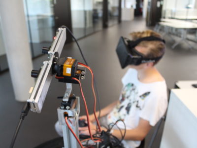
What would it be like to explore the world as a small kid? The quest of answering this question sounds like a perfect job for the Oculus Rift. For all those who don’t know the Oculus Rift, it is a display which you can wear on your head. Of course there have been already similar products before, but the Oculus Rift has some features for an extremely immersive experience:

  • A large field of vision of 100° to cover the most part of our vision
  • Precise head tracking, which allows measuring how the head is held
  • Good software development kit, which makes it easy to develop applications for it
  • Fast growing developer community

Most of the applications developed for the Rift are just rendering a virtual world. At the Institute i4Ds of FHNW School of Engineering I wanted to go a step further: Show the real world! For stereovision I have a wide-angle camera for each eye. To provide a natural way of looking around, the camera rig is attached to a 3-axis gimbal. As I look around with the Rift, the camera head does the same synchronously. But simply looking around is not enough; I wanted also to be able to move around. Therefore I installed this gyrating stereovision device on a robot platform. Furthermore, to make it easy to use, I wanted the IRE to be wireless.

The biggest risk in using the Oculus Rift is getting motion sick. Therefore I had to pay attention to some requirements. One is the need of a low latency, respectively the time from moving the head to getting the matching image. The other important requirement is a high frame rate, in this case 60 frames per seconds. All of these goals were very challenging, but in the end I succeeded and we built the IRE (Intuitive Rift Explorer) with these incredible key features:

  • One of the first moved reality systems
  • Gyrated camera rig, which is matching head movements
  • Remote-controlled robot
  • Large field of vision
  • Completely wireless
Do you want to know more how IRE was built? Start reading the blog series now.

IRE – Overview (Part 1 of 7)

IRE

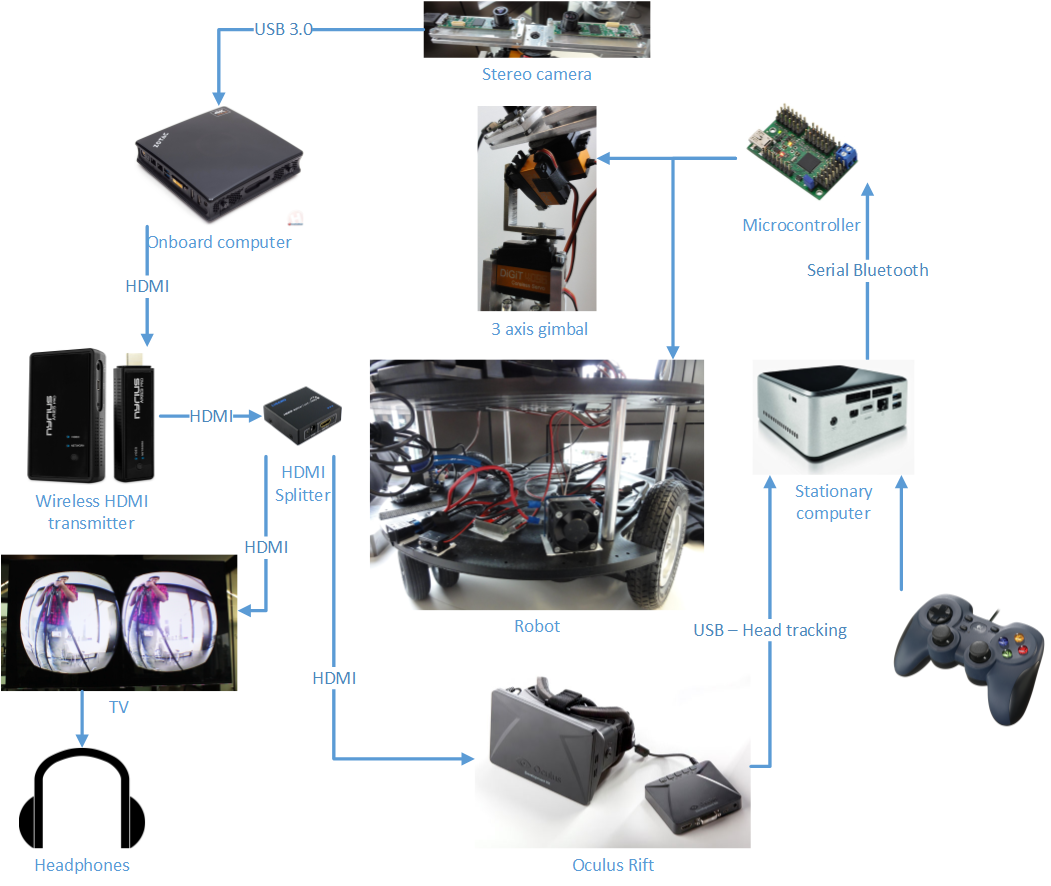
The post “May I introduce IRE?” has already explained the basics of what IRE is. This post will be the start of whole series of blog posts about my journey of doing this project.

Index

  1. Overview – This post.
  2. Stereo camera – Choice of camera module and how it is assembled to stereo cam.
  3. Video & audio transmission – Transmitting the video and audio wirelessly by Wireless HDMI.
  4. Media processing – Processing the live video of the stereo cam for the Oculus Rift and audio of the microphone.
  5. Camera Gimbal – Gyrating camera rig resp. head.
  6. Control system – System of processsing and transmitting the command controls for the gimbal and the robot.
  7. Conclusion – My very own conclusion about the Open Day and this project.

Diagram

The following diagram will give a short overview of the IRE’s system:

SystemDiagram

The whole system is split in two completely independent parts: a media system and a control system.

Media System

The media system is responsible for getting the image from the cameras Canada Lookup Telephone Numbers , processing (especially distorting the image for the Rift) and sending the image wirelessly to Oculus Rift. Additionally it also transmits the audio from microphone on the robot. It’s built from these parts:

  1. USB 3.0 Cameras: two See3CAMCU50 with
  2. Onboard computer: Zotac EI750 with Windows 7
  3. Wireless HDMI transmitter: Nyrius Aries Pro
  4. Oculus Rift DK1
  5. HDMI Splitter, TV & Headphones

Control System

As part of the control system, a stationary computer receives joystick input from the gamepad and head-tracking data from the Rift. After some calculations, the control signal is sent over Bluetooth to the servo controller. This sends the proper signal to the servos and motor controllers. Basically I used these parts:

  1. Head tracking of Oculus Rift and gamepad Logitech F310 input over USB
  2. Stationary computer: Intel NUC D54250WYB
  3. Serial Bluetooth: two connectBlue OBS421I-26-0 and one connectBlue ACC-34
  4. Servo controller: Pololu Mini Maestro 12-Channel
  5. 3 axis gimbal: 3 Savöx SH-1290MG
  6. Robot: Parallax Arlo Robotic Platform System

Costs and time

IRE was built for our open day at the University of Applied Sciences FHNW. I worked on this project full-time for three months; overall that adds up to about 500 hours. All the parts cost roughly 2500 CHF (or 2640 USD).


The next article will cover the choice of the stereo camera.

If you have any suggestions or questions, please use the comment form. I am always happy to learn something new.

IRE – Stereo camera (Part 2 of 7)

IRE

Camera mount - front
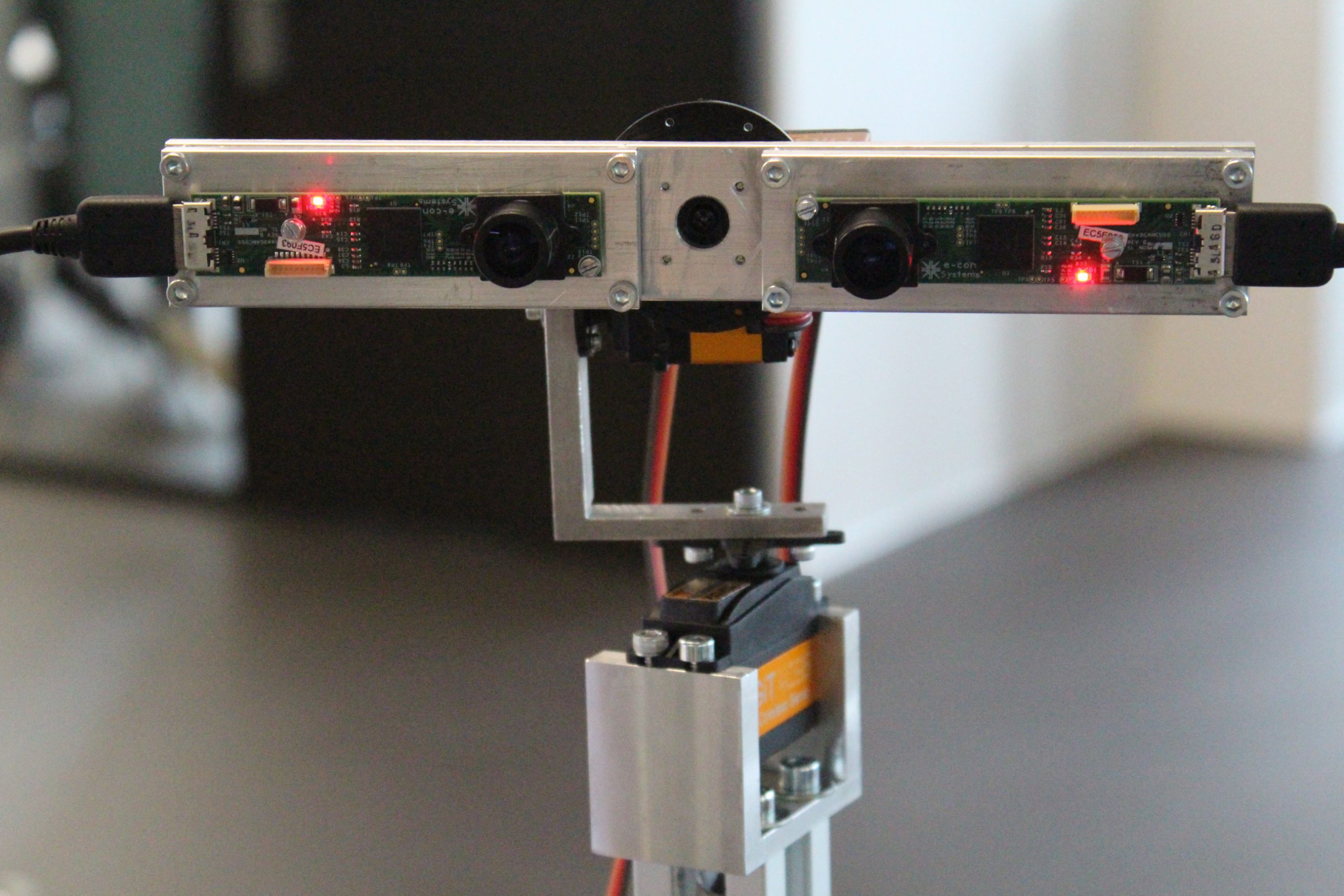
In order to match the Rift specifications as closely as possible, I had some very challenging requirements for cameras:

  • Stereo camera
  • Frame rate of 60 fps
  • Resolution at least 640×800 pixels (and for the Oculus Rift DK2 960×1080 pixels)
  • 90-degree field of view
  • Easily connectable to the onboard computer – probably USB
  • Affordable

Resolution IlustrationMost standard webcams, such as those made by Logitech, don’t have 60 fps. The famous PlayStation 3 Eye camera has that high frame rate, but only at 640×480 pixels. Most onboard cameras would have 60 fps, but they are difficult to connect because they don’t have USB. When I googled USB 3.0 cameras, I only found very expensive industrial cameras. Finally I discovered the trick of searching with YouTube. After a while I found the company called e-con Systems. They produce the camera See3CAMCU50. It features 60 fps at 1280×720 pixels over USB 3.0. Bingo! Additionally, any lens of a M12, or respectively S-Mount, can be installed. I went for two Lensation BT1922C lenses, which give me a field of view of about 90°.

As you probably already noticed, the resolution of the camera doesn’t match the resolution of the Oculus Rift. Regardless of which version of the Rift is used, either DK1 or DK2, some pixels are lost. Turning the camera 90 degrees does help to lose fewer pixels Canadian area code 779 , because then it has the resolution of 720×1280. The left image is an illustration of the different resolutions.

Camera mount

Camera mount - back

In order to get a stereo camera, the cameras are mounted on an aluminum plate. The lenses thereby have a separation of 65 mm, which is the average interpupillary distance in humans. The rig has the ability for tweaking the orientation of each camera to make sure that our brain can merge the two images into one stereo image.

See3CAMCU50

The See3CAMCU50 compresses the video stream with MJPEG in order to get 60fps. Of course the USB 3.0 connection isn’t the bottleneck, but the parallel interface connection from the chip to the USB controller is. This compression has some drawbacks. For example, the edges in the image are pixelated. Luckily the user won’t notice it very much, because the Rift DK1 is pixelated anyway. The bigger issue is the required CPU power to decompress the video stream. That’s the reason for choosing an onboard computer with an Intel i7. I should also mention that the cameras only work properly with Windows 7.

Today I wouldn’t choose the See3CAMCU50 anymore. I would probably go for the LI-USB30-M021X or the LI-USB30-M034WDR of Leopard Imaging Inc. They are more expensive, but the video stream isn’t compressed, so you could probably save some money on the computer.

My tests, however, have shown the importance of 60 fps. I also tried it with 30 and 40 fps with the Oculus Rift, but the results were horrible. The image is stuttering and you quickly get motion sick. In my opinion the high frame rate is vitally important to achieving a great experience.

The next article will cover the wireless video & audio transmission.

If you have any suggestions or questions, please use the comment form. I am always happy to learn something new.

IRE – Video & audio transmission (Part 3 of 7)

IRE

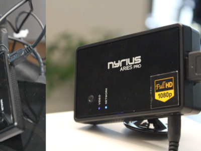
How can I wirelessly transmit 1080p@60fps with short latency? That was one of my biggest questions. Most FPV systems are analog, which results in a bad image. That’s why I wanted to have a digital solution. First I thought of using Wifi, but soon I realized that it would have too much latency. Some people reported having over 150ms. After advices of Oculus VR the motion-to-photons latency (time from moving head to the matching image) should be under 20ms. So Wifi wasn’t an option. Perhaps it would be possible to get the latency down with a lot optimizations, but I didn’t have the time for that.

NyriusAriesPro

After searching for a while, I found the standard Wireless HDMI. Most of the systems work on 5.1 – 5.8 GHz. I decided to take the Nyrius Aries Pro Canadian area code 902 , because it promised reasonable range (~40 meters) with <1ms latency. In addition the transmitter can be powered over USB. Because the transceiver acts like an HDMI cable, it also transmits audio. The downside is that the final image has directly to be transmitted to the Rift, so the video procession part has to be done on the robot.

In order to not only move the vision to another place, I added a microphone to the onboard computer. This sends the input to the HDMI output. To get the audio to some headphones, I put an HDMI splitter between the receiver and the Rift. The HDMI splitter was then connected to a Samsung TV, into which the headphones were plugged. In addition, the public could also see what the Rift-wearer sees.

I am quite happy with Nyrius Aries Pro; it has a feasible range to cruise in the office. But for an immersive telepresence robot, it will be necessary to find a solution for transmitting the video stream over the internet.

The next article will cover the processing the live video of the stereo cam for the Oculus Rift and audio of the microphone.

If you have any suggestions or questions, please use the comment form. I am always happy to learn something new.

IRE – Media processing (Part 4 of 7)

IRE

The special lenses of the Oculus Rift require the image to be distorted. This can be done with the official SDK. Its documentation is quite good, but luckily I’ve found the upcoming Oculus Rift in Action book with its nice source code examples. For my code I used the Hello Rift example as a base.

The application has two threads. On the main thread the OpenGL part happens – the camera image is loaded to the texture etc. The second thread is used for getting both camera images by OpenCV. To ensure that the two threads don’t mess each other up, a mutex and two conditional variables are used.

Camera thread

The cameras have two compression modes: YUV and MJPEG. With the standard OpenCV camera implementation, only YUV is available. For 60fps, however, the MJPEG mode is necessary. Therefore the DirectShow implementation in OpenCV has to be used. That can be accomplished by using a camera id from 700 – 799 and then setting FOURCC to MJPEG.

CvCapture* camLeft = cvCaptureFromCAM(700);
cvSetCaptureProperty(camLeft, CV_CAP_PROP_FOURCC, CV_FOURCC('M', 'J', 'P', 'G'));
cvSetCaptureProperty(camLeft, CV_CAP_PROP_FRAME_WIDTH, CAM_IMAGE_WIDTH);
cvSetCaptureProperty(camLeft, CV_CAP_PROP_FRAME_HEIGHT, CAM_IMAGE_HEIGHT);

CvCapture* camRight = cvCaptureFromCAM(701);
cvSetCaptureProperty(camRight, CV_CAP_PROP_FOURCC, CV_FOURCC('M', 'J', 'P', 'G'));
cvSetCaptureProperty(camRight, CV_CAP_PROP_FRAME_WIDTH, CAM_IMAGE_WIDTH);
cvSetCaptureProperty(camRight, CV_CAP_PROP_FRAME_HEIGHT, CAM_IMAGE_HEIGHT);

Our tests have shown that accessing the two cameras in separate threads results in worse performance than using one thread. In order for the camera thread to already request the new image while the current image is uploading to a graphics card in the main thread Area Phone Code 450 , the image is copied to dedicated image buffers.

// wait on draw thread
{
	unique_lock<mutex> lck(camMutex);
	while (!drawFinish && !terminateApp) { drawFinishCondition.wait(lck); }
}

imageLeft = cvQueryFrame(camLeft);
if (imageLeft) {
	memcpy(perEyeWriteImage[0]->imageData, imageLeft->imageData, CAM_IMAGE_HEIGHT * CAM_IMAGE_WIDTH * 3);
}
else{
	SAY("Didn't get image of left cam");
}

imageRight = cvQueryFrame(camRight);
if (imageRight) {
	memcpy(perEyeWriteImage[1]->imageData, imageRight->imageData, CAM_IMAGE_HEIGHT * CAM_IMAGE_WIDTH * 3);
}
else {
	SAY("Didn't get image of right cam");
}

long now = Platform::elapsedMillis();
{
	unique_lock<mutex> lck(camMutex);
	drawFinish = false;
	camFinish = true;
	camFinishCondition.notify_all();
}

Main thread

For each image there are two buffers. The pointers of them are swapped in the main thread as soon as the camera thread is finished. That way, it can be ensured that no screen tearing occurs. After the swapping, the camera thread is told to resume.

// wait for camera thread
{
	unique_lock<mutex> lck(camMutex);

	while (!camFinish){
		camFinishCondition.wait(lck);
	}
}

// swap image pointers
for (int i = 0; i < 2; ++i)
{
	IplImage* tempImage = perEyeReadImage[i];
	perEyeReadImage[i] = perEyeWriteImage[i];
	perEyeWriteImage[i] = tempImage;
}

// notify camera thread to resume
{
	unique_lock<mutex> lck(camMutex);
	camFinish = false;
	drawFinish = true;
	drawFinishCondition.notify_all();
}

In the meantime, the visible part of image is uploaded to the image OpenGL texture. Then the texture is mapped on a rectangle. This rectangle will be positioned and zoomed as necessary.

// only load necessary part of image
glPixelStorei(GL_UNPACK_ROW_LENGTH, CAM_IMAGE_WIDTH);
glPixelStorei(GL_UNPACK_SKIP_PIXELS, 189);

// bind and load camera image
imageTextures[eye]->bind();
glTexSubImage2D(GL_TEXTURE_2D, 0, 0, 0, RENDER_IMAGE_WIDTH, RENDER_IMAGE_HEIGHT, GL_BGR, GL_UNSIGNED_BYTE, perEyeReadImage[eye]->imageData);

glPixelStorei(GL_UNPACK_ROW_LENGTH, 0);
glPixelStorei(GL_UNPACK_SKIP_PIXELS, 0);

Finally the Oculus Rift SDK distorts the stereo image and the finished frame will be displayed on the screen.

You can find the whole code on GitHub.

Oh, and the audio: At the moment the microphone will just pass through to the HDMI with standard Windows settings.

The next article will cover the gyrating camera rig resp. head.

If you have any suggestions or questions, please use the comment form. I am always happy to learn something new.

IRE – Camera Gimbal (Part 5 of 7)

IRE

Camera gimbal with Oculus Rift

Of course I wanted to make use of Rift’s amazing head tracking and syncing the camera orientation with it. Using some static fisheye cameras to compute the right image for matching spot would have been neat. Such a solution would eliminate problems with quick head movement and latency. But omnistereo imaging is quite difficult for every possible head position. That’s why I decided to go for the mechanical solution: A camera gimbal.

Gimbals are now quite common in the drone scene for stabilizing cameras. Most of them use altered brushless motors, which are very fast, but not strong. One possible option would have been the DYS BLG3SN ($450). Likely it would have been a problem with the thick USB 3.0 cables of the cameras. It would have been nearly impossible to balance the brushless gimbal, which is necessary. Another possibility would have been using a servo gimbal, like the Tarot 3-Axis Gimbal ($600). All these gimbals are controlled with a proprietary microcontroller. It wasn’t clear to me whether there was an option to send commands to move the gimbal to a specific point, or with what frequency the commands could be emitted. The head orientation for the Oculus Rift can be gathered with 1000 Hertz. To minimize latency, the gimbal has to be updated as often as possible.

DIY

Camera Gimbal backAfter careful deliberation, I decided to avoid all of these potential pitfalls and build the camera gimbal myself. The archetype for my own gimbal was the Fatshark Pan, Tilt & Roll System. As a servo I chose the Savöx SH-1290MG, because it is very fast (0.048 seconds for 60°) and strong (5kg/cm). In addition phone Numbers lookup , the control command can be sent with 333 Hertz. Luckily the workshop at my university was able to build the gimbal and they ended up with the solution visible in the image shown here. It works quite well; only the pitch servo seems to be overloaded, as it is a bit stuttering. But with the Oculus Rift on, it wasn’t a big issue. More concerning is the missing image stabilization. While driving the video is annoyingly jerky.

The next article will cover the system of processsing and transmitting the command controls for the gimbal and the robot.

If you have any suggestions or questions, please use the comment form. I am always happy to learn something new.

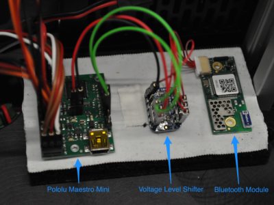
IRE – Control system (Part 6 of 7)

IRE

IRE ElectronicsThe last post covered how the video signal is transmitted. However, a communication channel back to the robot is also necessary. Over this channel the signals for the gimbal and the robot are sent. The smartest solution would have been to transmit the USB of the Oculus Rift and the gamepad directly to the onboard computer. In fact, there are a few Wireless USB systems out there, but all have high latency. That’s why I decided to do the processing of these inputs on a stationary computer and only send the control commands to a microcontroller on the robot. But what wireless technology has low latency and a reasonable range?

Bluetooth

A bit of internet research shows that the latency of WiFi and Zigbee is too high. I asked an electrical engineer at my university and he recommended using Bluetooth modules by the company u-blox. These are optimized for short latency and as well as a long range. I took his advice and bought two connectBlue OBS421I-26-0 and one connectBlue ACC-34. The ACC-34 is just a serial-to-USB adapter to connect the Bluetooth module with the stationary PC.

Maestro Mini

To drive the servos of the gimbal and robot motors, I used the fantastic Pololu Mini Maestro 12-Channel board. It has many setting options, simple serial protocol and is able to output the servo (PWM) signal with up to 333Hz.

Code

The application on the stationary computer is written in C++. With DirectX’s XInput interface it reads the analog stick of the gamepad and converts it to command controls for the robot.

short stickY = _gamepad.GetControllerAxis(Gamepad::LEFT_Y);
short stickX = _gamepad.GetControllerAxis(Gamepad::RIGHT_X);

short leftMotorInput = (stickY + stickX) / 2;
short rightMotorInput = (stickY - stickX) / 2;

// faster forward driving
if (stickX == 0) {
	leftMotorInput = stickY * 0.8f;
	rightMotorInput = stickY * 0.8f;
}

thisLeftMotor = Maps(leftMotorInput who call Telephone Numbers , GAMEPAD_MIN, GAMEPAD_MAX, LEFT_MOTOR_MIN, LEFT_MOTOR_MAX);
thisRightMotor = Maps(rightMotorInput, GAMEPAD_MIN, GAMEPAD_MAX, RIGHT_MOTOR_MIN, RIGHT_MOTOR_MAX);

The Oculus Rift SDK is used to get the head orientation. It returns a quaternion, which easily can be converted to Euler angles. After some correction and tuning these are used to control the gimbal.

You will find the whole code on GitHub. The control system’s code is in the project IREController.

Goodie: Commander Control

Commander ControlBecause we also wanted to use the system with a broad audience, I needed a handy control to pause the system before someone damages it. Because I didn’t want be bound to a keyboard, I used a standard wireless presenter. The presenter just sends normal key commands, which I only had to map to the functions.

The next article will be the last one. It contains my conclusion of the Open Day and the project.

If you have any suggestions or questions, please use the comment form. I am always happy to learn something new.

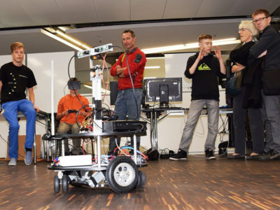
IRE – Conclusion (Part 7 of 7)

IRE

Image of our Open Day from the local newspaper AZ

Overall I was really impressed with how well the system worked British Columbia , and was also rather proud of myself. As I built it for our open day, the system had to work all day long with many different people. In this regard it worked perfectly – the children especially went crazy for it; it was even difficult to get them out of that moved reality. I think we were able to inspire many children to become computer scientists themselves.

As I built IRE in a short time period, I only focused on the must-have features. As a result, the system isn’t easily extendable. For example, we had the idea to add an HUD overlay over the image for better orientation. In that case I found the workaround in installing a pole in front of the camera system. But as the media and the control system are very independent parts, the media system doesn’t have the head-tracking information of the Oculus Rift. Somehow the media and control system need to fuse on one computer. That would probably be the most cost-effective solution. As a workaround we will probably add a data channel from the stationary to the onboard computer.

People

Without the help of many people, this project wouldn’t have been possible. I want to thank (in alphabetical order):

  • Daniel Binggeli (Bluetooth)
  • Roman Bolzern (Optimization)
  • André Csillaghy (man in charge)
  • Livio Del Negro (Wiring & electronic)
  • Simon Felix (Optimization)
  • Juliet Manning (Lector)
  • Stefan Müller Arisona (OpengGL)
  • Lukas Portmann (Mechanic)
  • Simon Schubiger (OpenGL)
  • Christoph Stamm (Camera & lens)
  • Simon Vogel (Electronical advisor)
  • Benjamin Wingert (Testing & advises)
  • LA Worrell (movie)

If you have any suggestions or questions, please use the comment form. I am always happy to learn something new.